Terrain Designer

This page shows programs that deal with visualizing and designing landscapes interactively.
I started to become interested in landscape applications during my time as a research assistant under professor Christophe Girot at ETH Zurich's Department of Landscape Architecture.
Below you can see the progression of my personal projects and teaching tools.


Terrain Designer

2024

TD_tdImgA
TD_tdAnmA TD_tdImgB

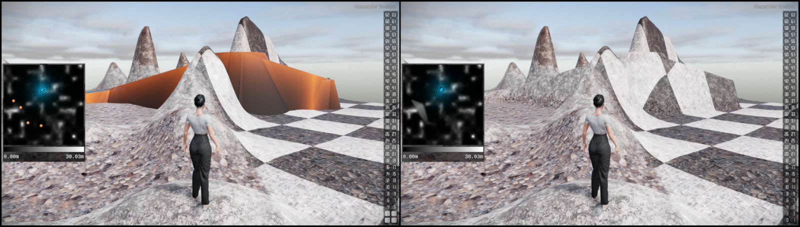
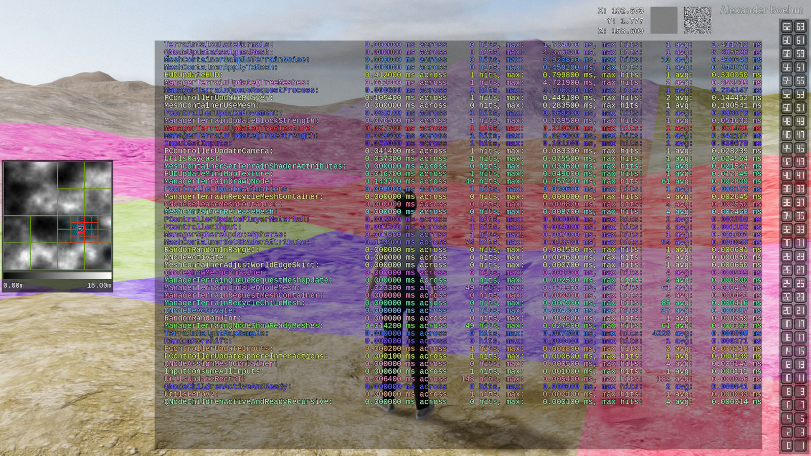
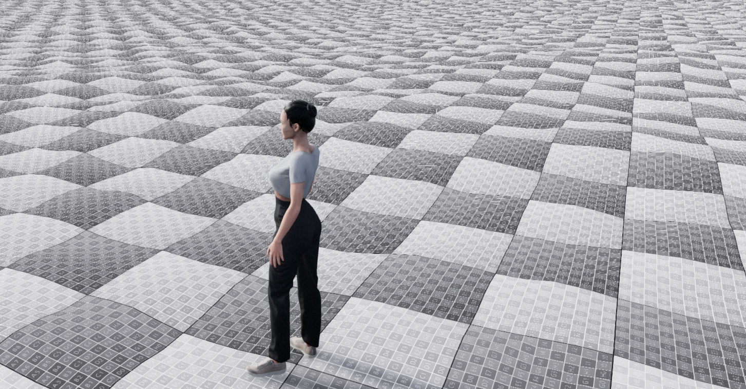
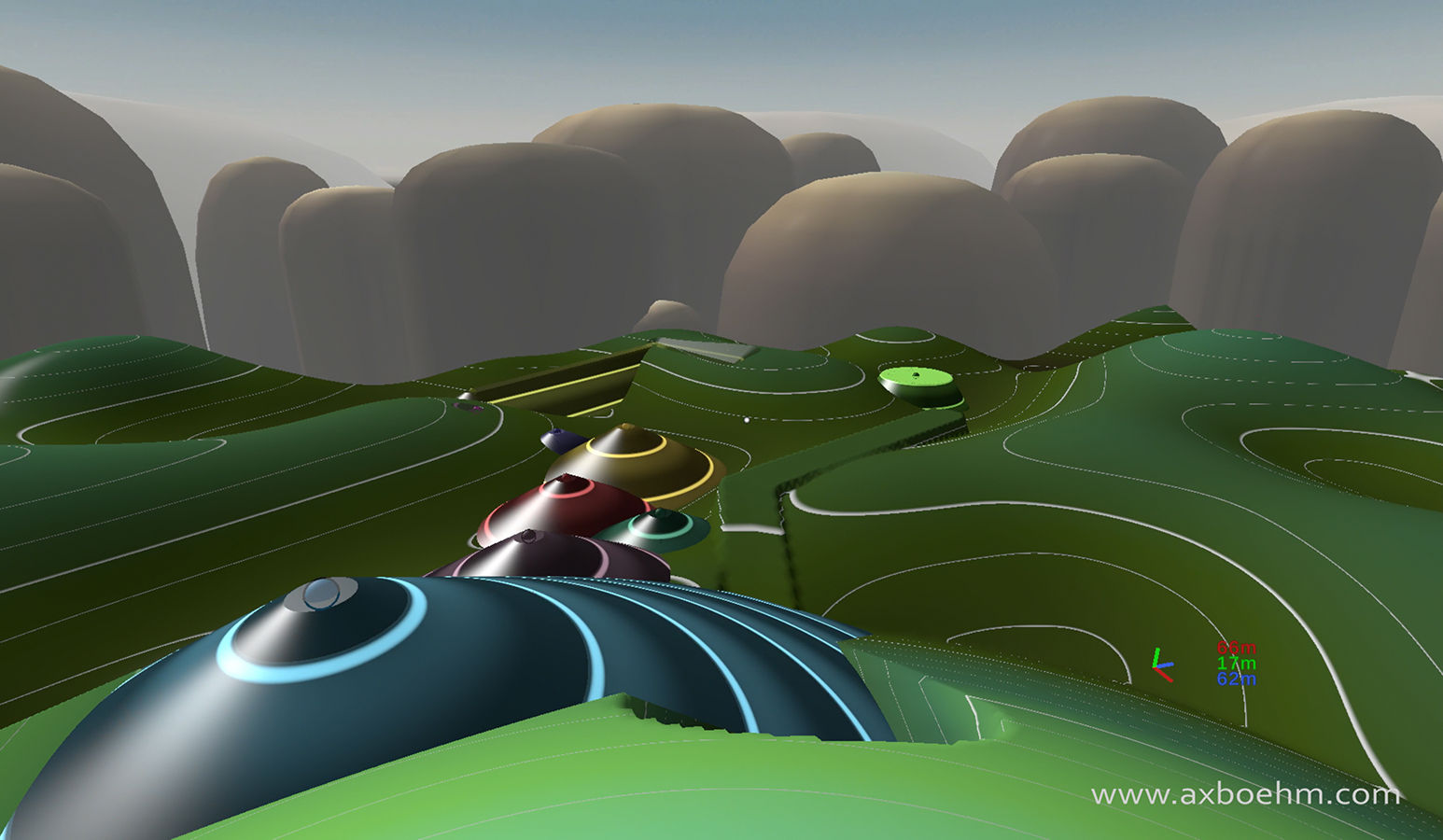
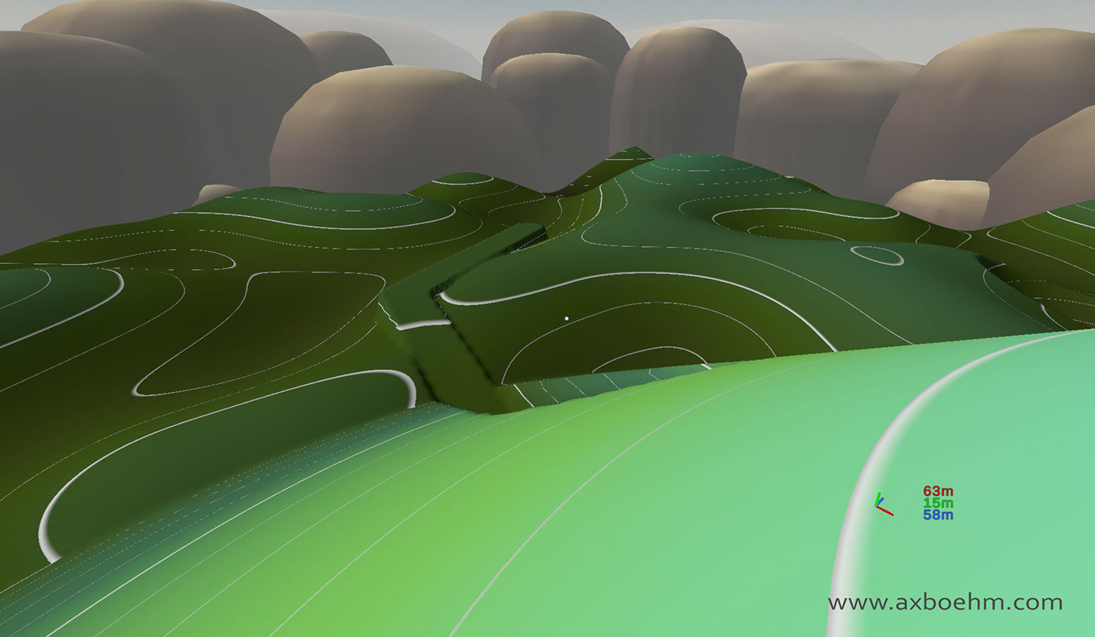
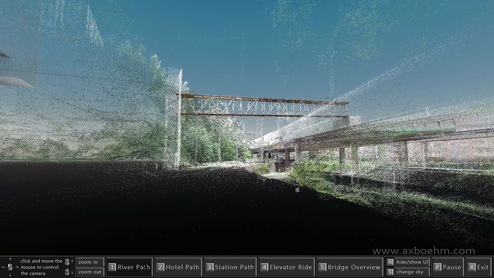
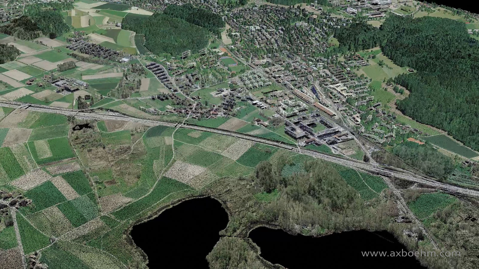
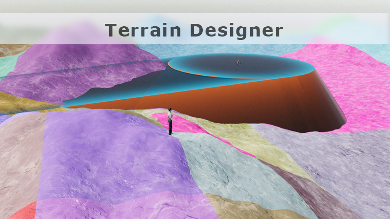
Terrain Designer is a 3D application that lets you walk around a landscape and modify it interactively and in real-time.
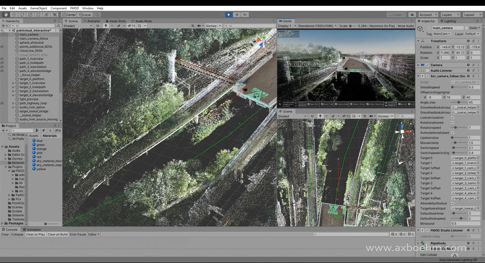
The application uses the Godot game engine v.4.2.1 for rendering and collisions and is written in C# and Godot shader code.
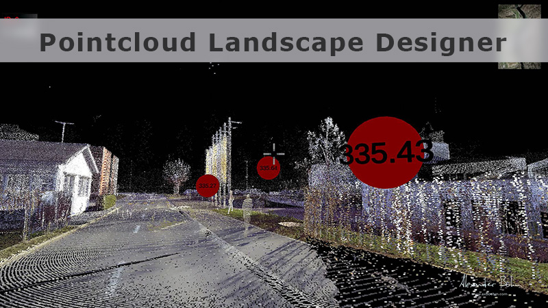
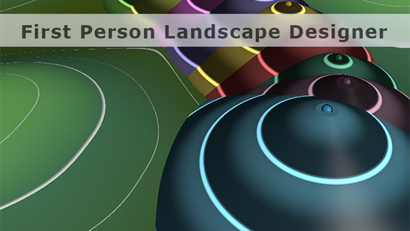
It is my latest interpretation of an interactive landscape design tool and an evolution of the other projects on this page.

I have made the code publicly available. Take a look if you are interested.

Find my code on github.

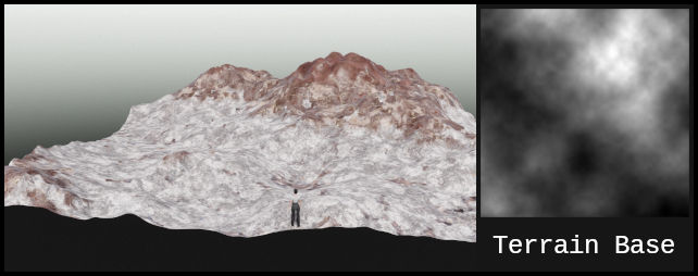
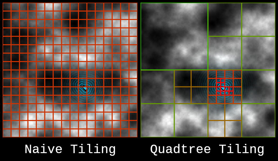
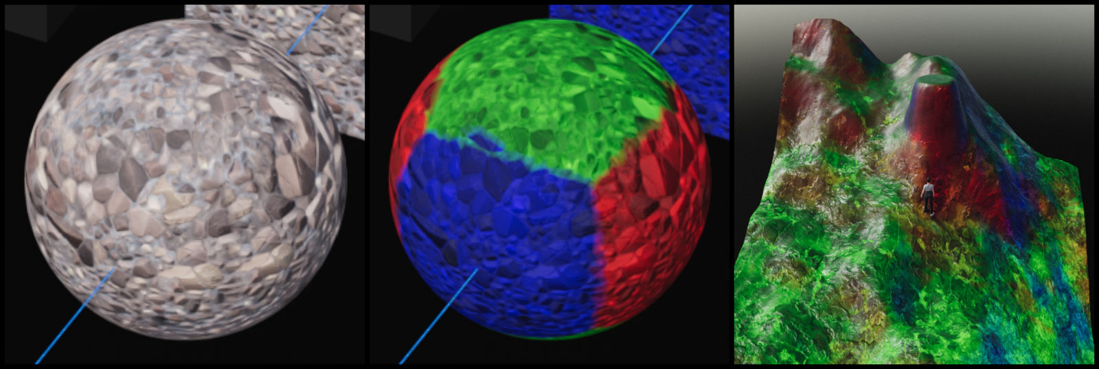
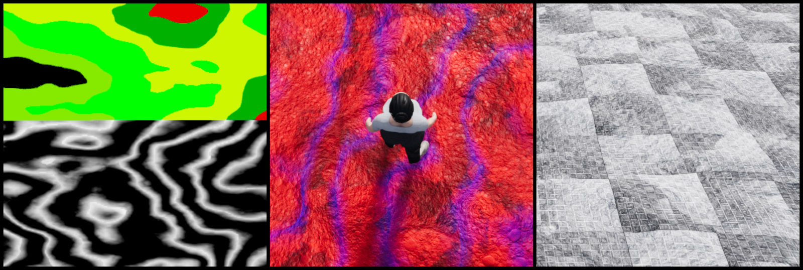
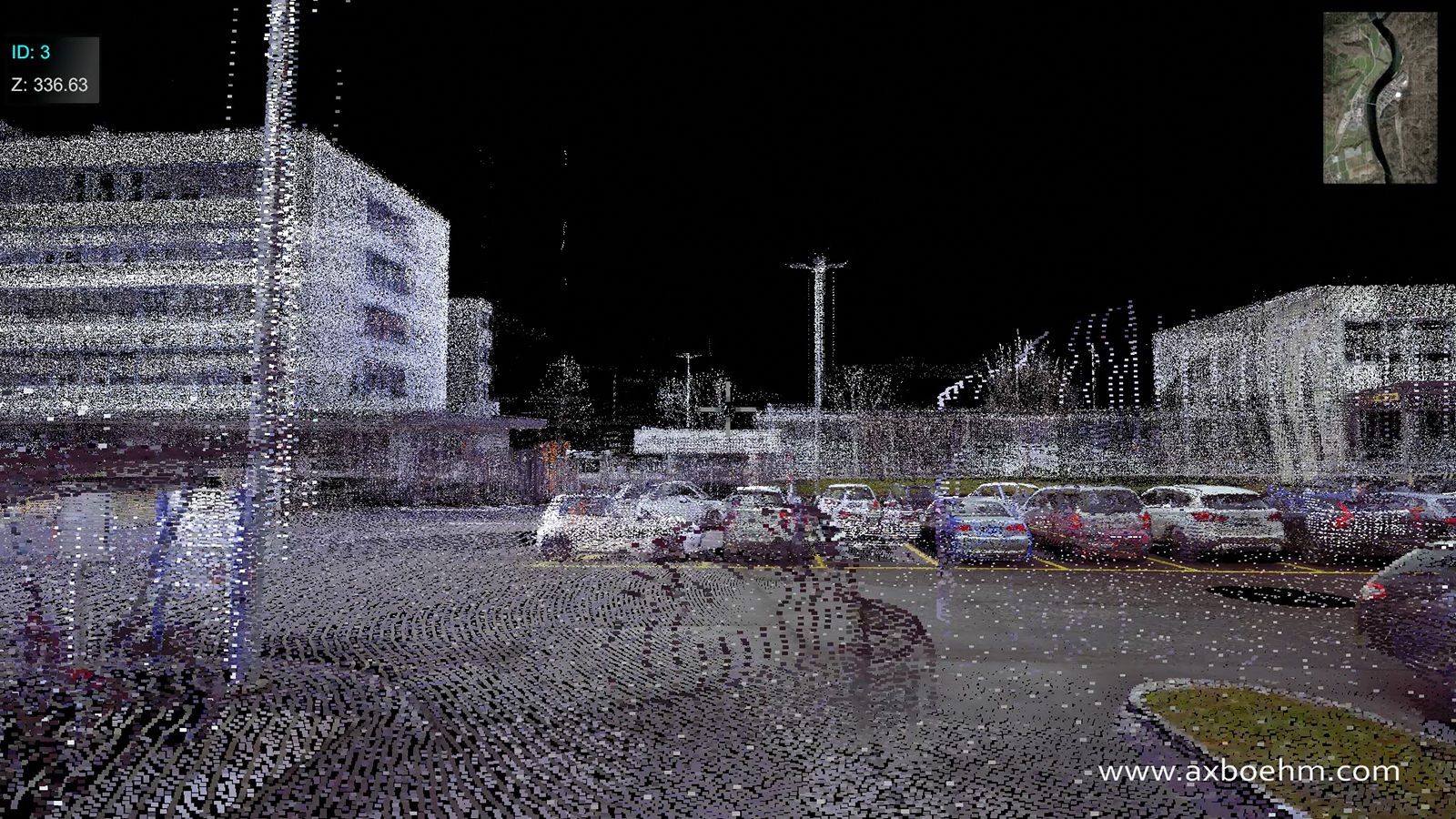
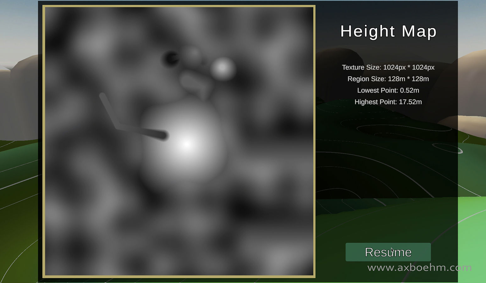
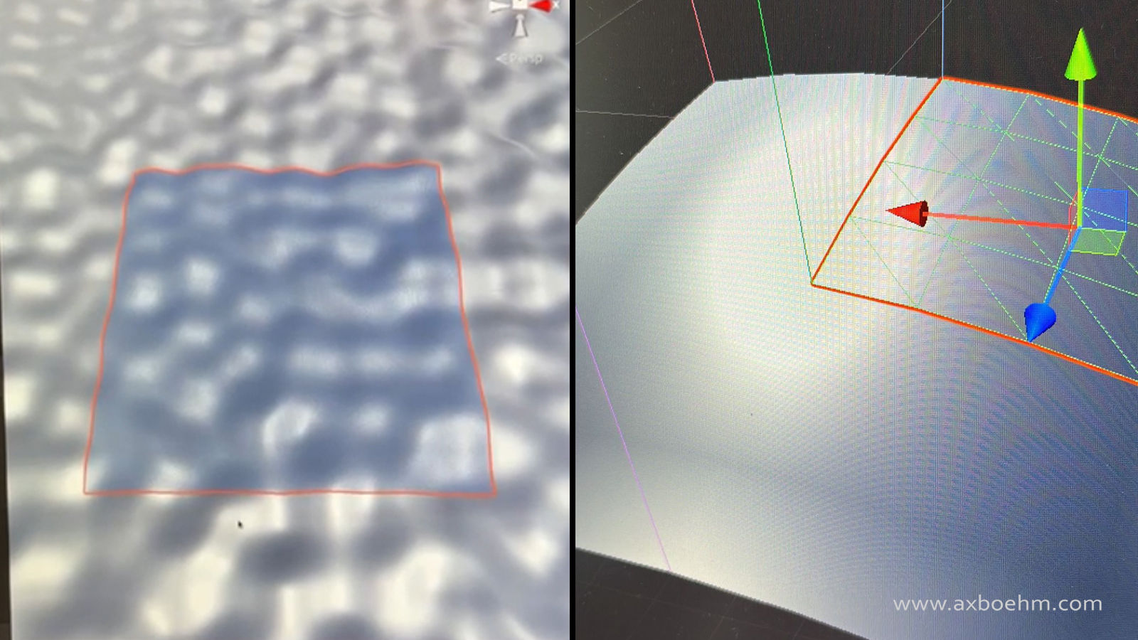
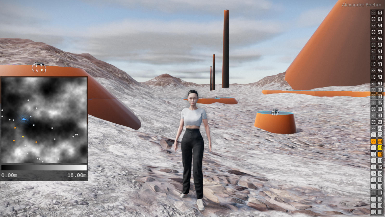
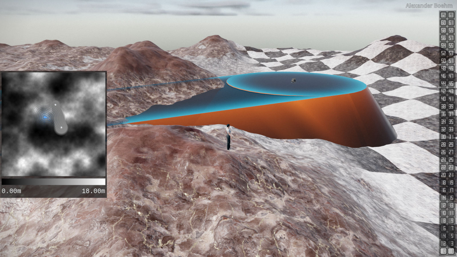
The terrain in the application is represented by a heightmap. Each coordinate of the terrain corresponds to a location on a 2D texture with the brightness at that point defining how high the terrain is at that coordinate.

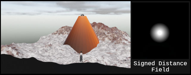
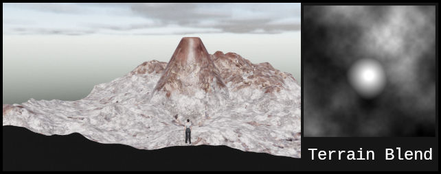
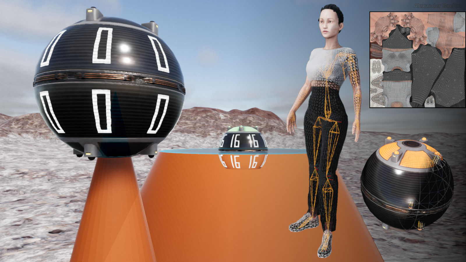
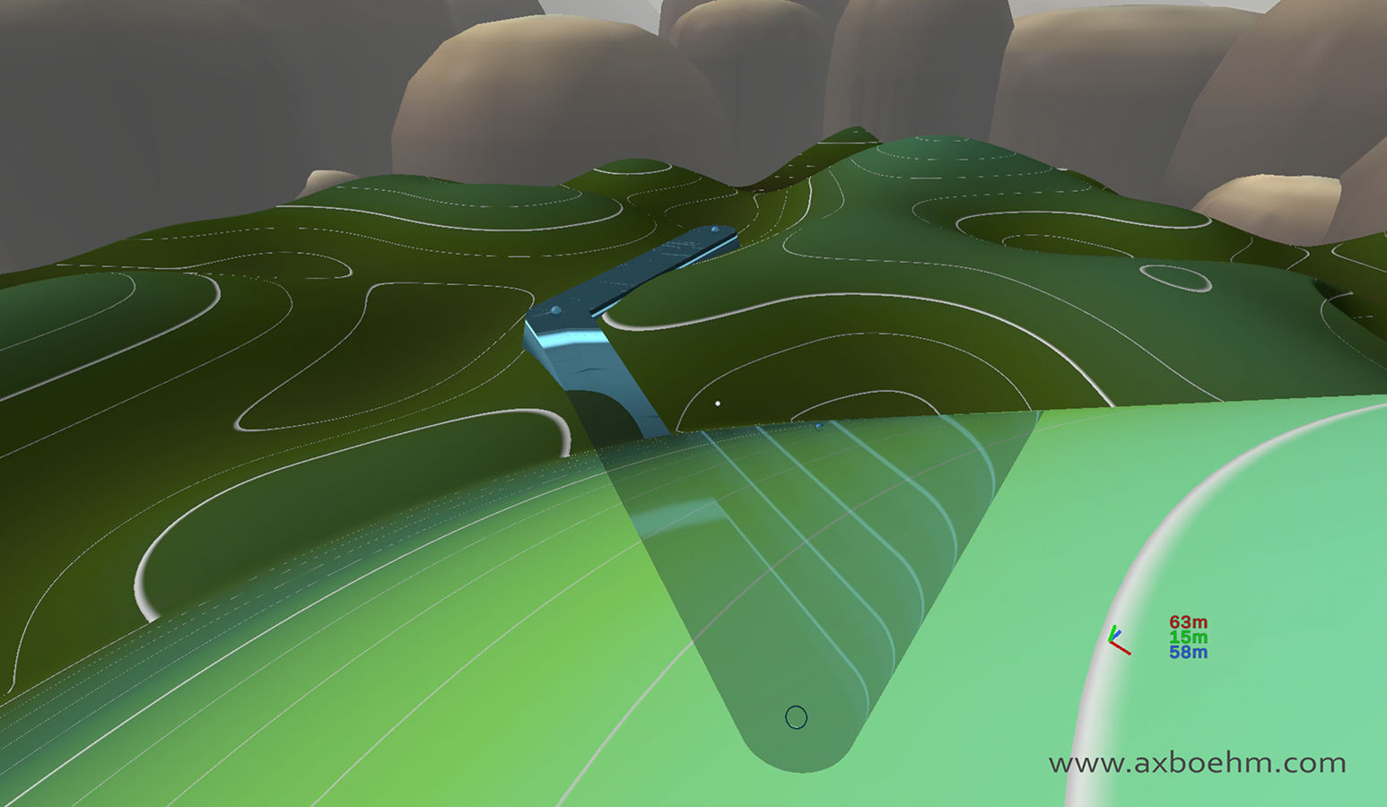
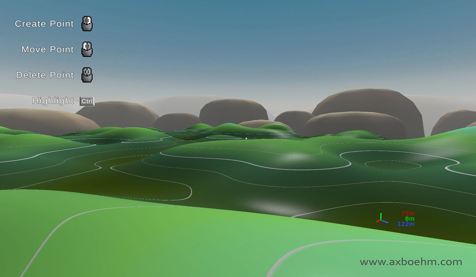
To allow the user to modify the terrain, intermediate geometry can be created and modified by the user in real-time which can then be permanently applied to the terrain.
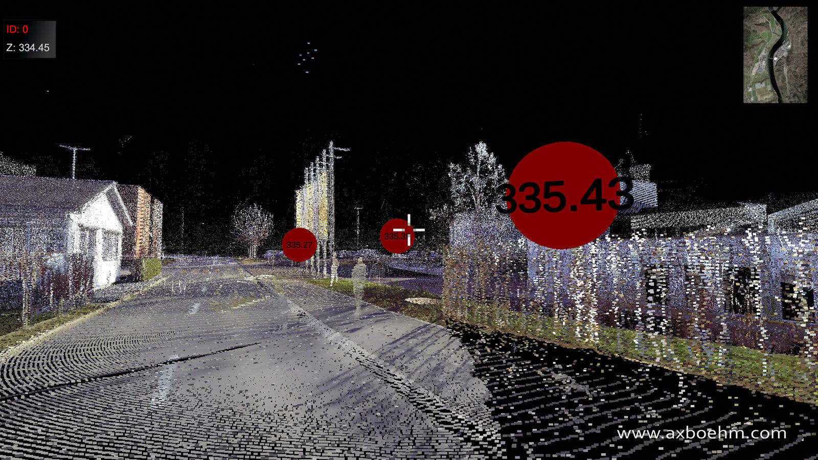
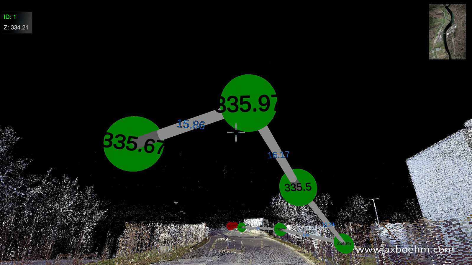
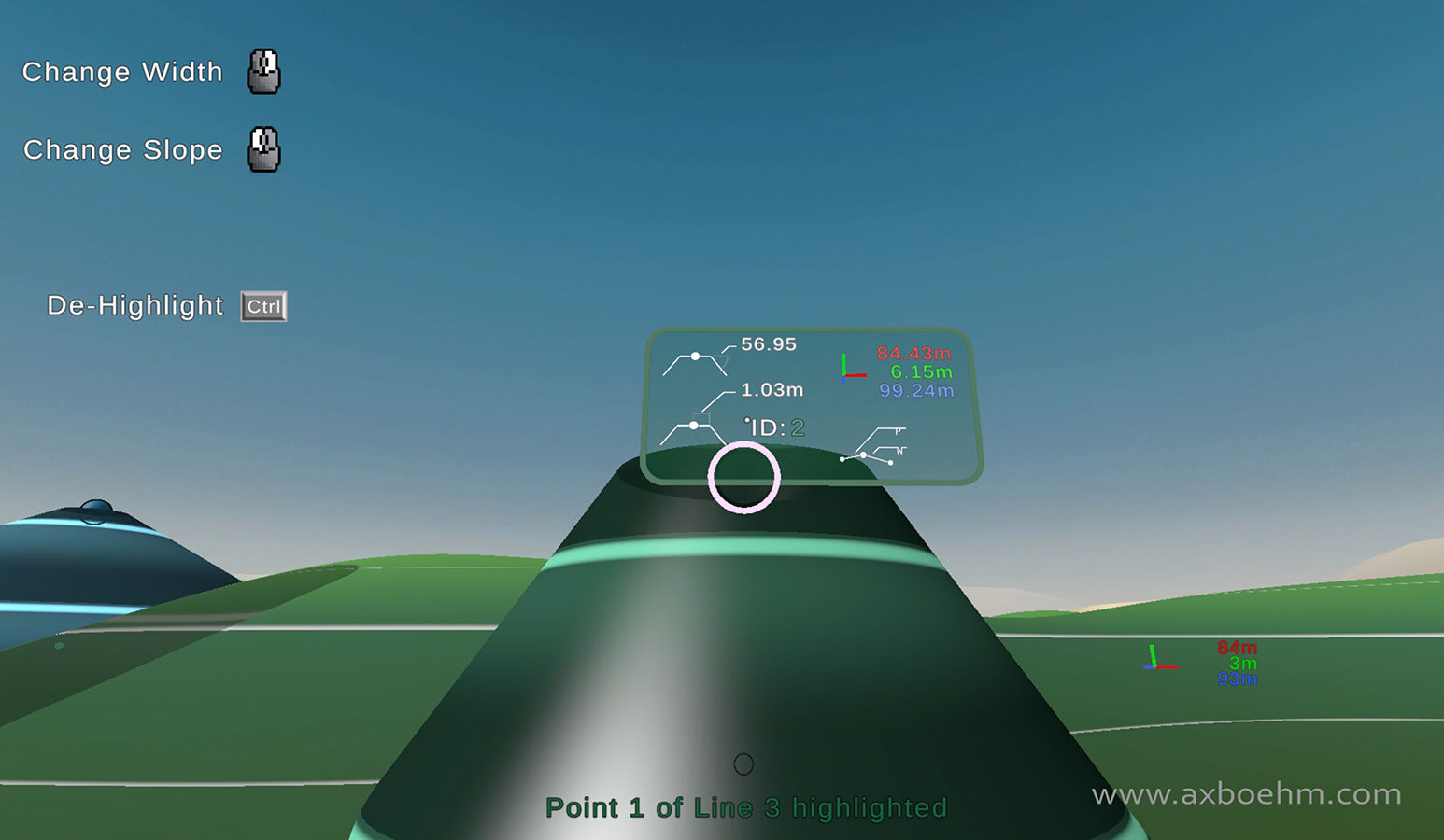
Spheres serve as control points for this intermediate geometry. Each sphere defines the tip of a cone. The cone can have a truncated top to form a platform. Both radius of that platform and the angle of the cone can be adjusted.
Spheres can also be linked together to add additional connecting geometry.

TD_tdImgN
TD_tdImgI TD_tdImgJ TD_tdImgK

To apply the modifications to the terrain, heightmaps representing different modifications get blended together.
Additional heightmaps representing the intermediate geometry are created and then blended together with the heightmap of the terrain.
This is done twice, once to add to the terrain using a maximum comparison and once to cut into the terrain with a minimum comparison.
The resulting geometry is higher where the intermediate geometry was above the terrain and lower where it was below it.

After modifications, the terrain samples an updated heightmap.
The mesh itself does not have to be entirely recreated as the topology of the terrain stays exactly the same. Only the vertical height coordinate changes.
Geometry for the terrain is created by having four arrays of data:
The vertices (3D position of the points that make up the mesh).
The triangle indices (which vertices of the previous array form a triangle together).
The UV coordinates (2D value between 0 and 1 to decide how textures are mapped to the geometry).
The normals (3D vector that defines the surface normal).
When the terrain gets changed, only the vertices and normals need to be recalculated, so a lot of computation can be skipped.

TD_tdImgO
TD_tdImgP

Given my design goal of creating a real-time application with good performance even for large landscapes, a large emphasis was put on how to represent the terrain's geometry.

To keep the framerate of the application high, even when running on modest hardware, the factors with the highest performance impact should be determined and then optimized.
As a first step, I implemented a custom profiler and overlay that times each function every frame and shows the sampled values along with their maximum values over the last few seconds.
This was fundamental in determining exactly which functions took the most time and how often they were called each frame, the amount of calls was just as important as the profiled times as it allowed me to judge the likelihood of lag spikes.

Two factors stood out which had the largest impact on performance:
The amount of vertices on screen, so the fidelity of the geometry.
And creating objects and assigning data to them.
The second one was especially problematic if it happened multiple times a frame, causing a large frametime when the application was otherwise running fine.

To improve on these two factors, I used three main strategies:
Avoid creation of new objects at runtime whenever possible and rather re-use existing ones.
Stagger creation of new objects (if it can not be avoided) and allocation of data over multiple frames to spread the load and avoid lag spikes.
Implement a custom quadtree representation of the terrain mesh to reduce vertex count while maintaining high fidelity around the user, where it actually matters.

TD_tdAnmB TD_tdImgH

The idea for the quadtree representation is based on recursive subdivision of the mesh.
The rootnode of the tree represents the entire terrain as a single tile with very low resolution. The next division level down (four children of the root) represent one quarter each with a higher resolution than the parent. This division continues to a specified depth until finally the leaf nodes of the tree represent only small parts of the mesh with a high resolution.
At runtime, my algorithm determines each frame, which tiles of the tree should be shown and hides parent and child nodes that should not be seen.

The result is a mesh with more detail close to the user and less far away from it. Resulting in a much lower vertex count compared to the naive method of equal tiles.

The tree is fully created at runtime but does not contain any mesh data yet, only the sizes and resolutions of the tiles.
So two structures exist in the application, a "sparse" quadtree with only the relational data stored in it and a list of the meshdata that gets assigned to quadtree nodes when they are active and recycled when they are not anymore.
When a tile is supposed to be shown, a request for the corresponding mesh is queued. The queue processes a certain amount of mesh calculation and assignment each frame and replaces a tile when it and all its dependants are ready.
Additional logic was required to make sure that no gaps appeared in the terrain, as replacing a tile with four subdivided tiles requires all four of those tiles to be ready first.

TD_tdAnmC TD_tdAnmE TD_tdAnmD
TD_tdImgE

When dealing with 3D objects, especially when designing with them, it is imperative to understand the scale of the objects we are working with.
The human character was added to give context to the terrain close to the camera. The design of the sphere helps with that as well, details like cables whose scale can be easily interpreted were added to its surface.

Just as important, especially for the distant areas is the terrain and its shader.
Since the terrain is calculated at runtime, my shader needed to support any geometry and function with large and small terrains alike.

TD_tdImgQ

The shader uses a custom terrain shader that blends between four materials that I created in Substance Designer.
Each material is comprised of four tiling textures: Diffuse, Roughness + Metalness, Normal Map and Height Map.
The scale of each material is absolute, so will appear to be the same scale no matter how large the terrain is.
The shader then blends between them to create an adaptive material by using the terrain's heightmap (calculated in code).
The height maps of each of the materials are considered for more realistic transitions between materials.
Triplanar mapping was implemented to prevent texture stretching on near vertical surfaces.

TD_tdImgR TD_tdImgF TD_tdImgG TD_tdImgG

These techniques create a shader that has all the properties laid out before but has one remaining flaw.
Since the textures tile repeatedly to fill the terrain, repetitions are quite noticeable.

To break up the visible repetition of textures, a technique called "Texture Bombing" is implemented.
The basic idea is to divide the UV space (so the way a texture is mapped to a mesh - 2D vector per vertex that represents which part of a texture should be sampled at that vertex) into cells and then offset the UVs in each cell randomly.
The challenge then is to avoid sharp edges and making sure that the edges of these cells blend together smoothly.
For more information about the basic concept texture bombing, take a look at this article by R. Steven Glanville written for NVIDIA's GPU Gems series.

In my implementation, I am using a random noise generated using Godot's noise implementation and then subdiving that into eight separate bands, so instead of using equal grid cells I am dividing my UVs into eight continuous bands.
Each band has randomly offset UVs and towards the edges of each band they are blended together to make the result appear seamless.

The result is an adpative terrain shader blending multiple materials based on height that can work with any geometry and at any scale.

My terrain shader code on github.

TD_tdImgD

All textures and models were created from scratch by me.
3D models were created using Blender, ZBrush and Marvelous Designer. UVs, rigging and animations were done in Blender.
Textures were made using Substance Designer, assets were textured using Substance Painter and Blender.
Some textures, such as those for the terrain and UI are created in code at runtime of the application.


Pointcloud Landscape Designer

2021 - 2022

TD_pcdImgA
TD_pcdImgB TD_pcdImgD

This application allows users to explore a digital clone of a real landscape. While navigating the environment, they can place control points in 3D space which can later be used to generate paths, dams, valleys and hills. It is made using the Unity Game Engine.

The goal was to create an interactive landscape design tool that brings the user closer to designing while being inside the landscape rather than being far away from it and having to abstract its representation.

The software was developed in cooperation with Benedikt Kowalewski of ETH Zurich to aid with his PHD thesis. It was also used by students during the design semester at ETH Zurich. Their task was to propose a landscape design for a large research campus in North-Eastern Switzerland.

Benedikt and I collaborated on how the software should behave and how it would be used. The code and implementation were then done by me.
The software can be used with mouse and keyboard or using a VR headset and controllers to walk around a georeferenced pointcloud environment and place control points and paths interactively.
Those points can be used in additional software to generate a new topography for the landscape. This can be loaded back into the application and continually modified.

The digital clone of the landscape is based on LiDAR laser scans which were turned into a georeferenced pointcloud and is to scale with reality. The accuracy of the representation is thus very high.
The walkable ground is based on a mesh generated from the pointcloud.

TD_pcdImgC

Navigation is possible by walking around and by teleporting to a position in the vicinity or by using the minimap.

There are two pointclouds in use. The first one has a low resolution, which is always present. The second one has a high resolution, which is split into square patches that are loaded in when the user is nearby.

TD_pcdImgE

The control points are stored in .xyz format with their ID and position. Points belonging to the same ID form a path. Points with ID 0 are stand-alone.
Their positions are relative to a georeferenced origin and can thus be used to find real world positions in the model.
In the same way a new point can be added manually by writing its position in the file to get a point at an exact position in the landscape.
Storing points in this way allows them to be used in other applications easily.

TD_pcdImgF TD_pcdImgG

In a seminar at Aalto University in Finland, students used the software we created in combination with a georeferenced stick to create a landscape design for their campus.
The application was run in VR mode. The students formed teams of two and while one was using the application, the other was in the landscape with the stick. Both could then create their design together.

The stick was made by Benedikt Kowalewski and continually sends its GPS position to a server running in the cloud.
I had modified the application to fetch that the data from the cloud server at regular intervals and display a reference stick in the application. The time from sending the signal to receiving it in the application was only a few seconds and could barely be felt while using it.
Users can then create a new point at the position of the stick or place others in reference to it.
The workflow only works because the pointcloud in the application is georeferenced as well.


First Person Landscape Designer

2022

TD_fpdImgA
TD_fpdImgC TD_fpdImgD TD_fpdImgE

This standalone landscape design tool is an evolution of the previous, pointcloud based version. It is made using the Unity game engine.
Instead of a pointcloud, the landscape consists of an evenly divided ground-mesh that can take any topography desired to begin with. Existing, scanned topography can be used just as well as a randomly generated ground or simply a flat plane.
The user can then navigate the environment and place and move points around in first person view.
These points are used to create new terrain that can be used to modify the existing topography.
The landscape is to scale and lines in the terrain form every five meters to help convey the realistic scale.
By using a visible ground mesh, the process of modifying the landscape can be included in the same application that is used for manipulating the control points using code that I wrote. The design loop could thus be greatly sped up compared to the previous version.

A heightmap of the terrain can also be generated. A heightmap is a greyscale texture representing an area of the landscape. Each pixel stores the corresponding point's height information relative to the medium height of the sampled area. A neutral grey thus means no deviation from the middle point, whereas brighter values represent elevations and darker values represent recessions.
To reproduce the same landscape, the lowest and highest points need to be known as well, as well as the dimensions of the area it represents, as a heightmap has no scale of its own.

The heightmap is created in code by performing ray casts from above at even intervals and comparing those heightpoints with the minimum and maximum height present in that mesh region.
The distance between the sampling points is defined by the resolution of the heightmap texture, which can be set to any desired resolution.
This software can be used to generate 3D shapes and turn them into displacement heightmaps that can then be repeatedly placed on the topography using simple mesh displacement.

TD_fpdImgF TD_fpdImgG

The user has a lot of options to modify the landscape. The system is based on control points that can form paths or triangles.
Control Points represent cones or dams if they are connected. They have properties for the radius of their plateau and the angle of their slope. They also show their position and the angle toward the previous and next point if they are part of a path.

Generating the geometry from these points works above and below ground.
Paths of multiple points can even combine the two, with some points above and some below ground. The algorithm I wrote will then generate the resulting shape.
Properties can be set for each point along the path separately, giving a lot of flexibility.

To aid users in working in this visually more abstract environment, I wrote a series of custom shaders that would make it easier to get a feeling of the 3D environment and its scale.
The terrain itself has horizontal lines at regular intervals that slice through the landscape and show the user where the same height is in different areas. There is also a gradient on the terrain, that will dynamically adjust to spread from the lowest to the highest point.
I wrote similar shaders for the new geometry, always with the goal of making the resulting geometry easier to anticipate.

TD_fpdImgH

To reduce unnecessary calculations and increase application performance, the terrain mesh is split into tiles which can have any resolution desired.
To preserve the integrity of the mesh and avoid cracks where tiles meet, I wrote custom code that would align mesh tile edges with each other.
Splitting the ground mesh up also required me to write code to recalculate each triangle's normal vector. With default behavior, the connection between mesh tiles would not be continuous and appear like a fold in the surface.

When the ground mesh gets updated to reflect the modification that the user made, only the tiles that would need to change will be updated. My code selects the necessary tiles based on the bounding box of the custom geometry to minimize superfluous processing.


Interactive Pointclouds

2019 - 2020

TD_ipcImgB
TD_ipcImgA TD_ipcImgC

Before I made the landscaping tools, I worked on making pointcloud viewers more interactive and easier to use. I used the Unity game engine.
This ranged from making camera animations easier to manipulate by making them follow bezier paths with control points to combining multiple animations in a single application and making switching between them easy and smooth.

I also tried to make the applications interesting even without user input by creating automatic camera movements that the program falls back to after some time without user input.
Making those transitions smooth for the viewer and easy to set up for the designer was a priority for me.
Some quality of life features were also implemented, such as pausing all animations, support for multiple sky maps, on-screen controls for first time users and a photo mode without any UI elements.